AVR programming with Arduino
Written by Victor van Poppelen.
The Arduino Nano
The Nano is a very simple board, essentially just an AVR MCU with an FTDI chip for communicating over USB. On the top left of the schematic1 is the pinout of the board, and in the centre is the pinout of the AVR chip (an ATmega328 or ATmega328p)2.
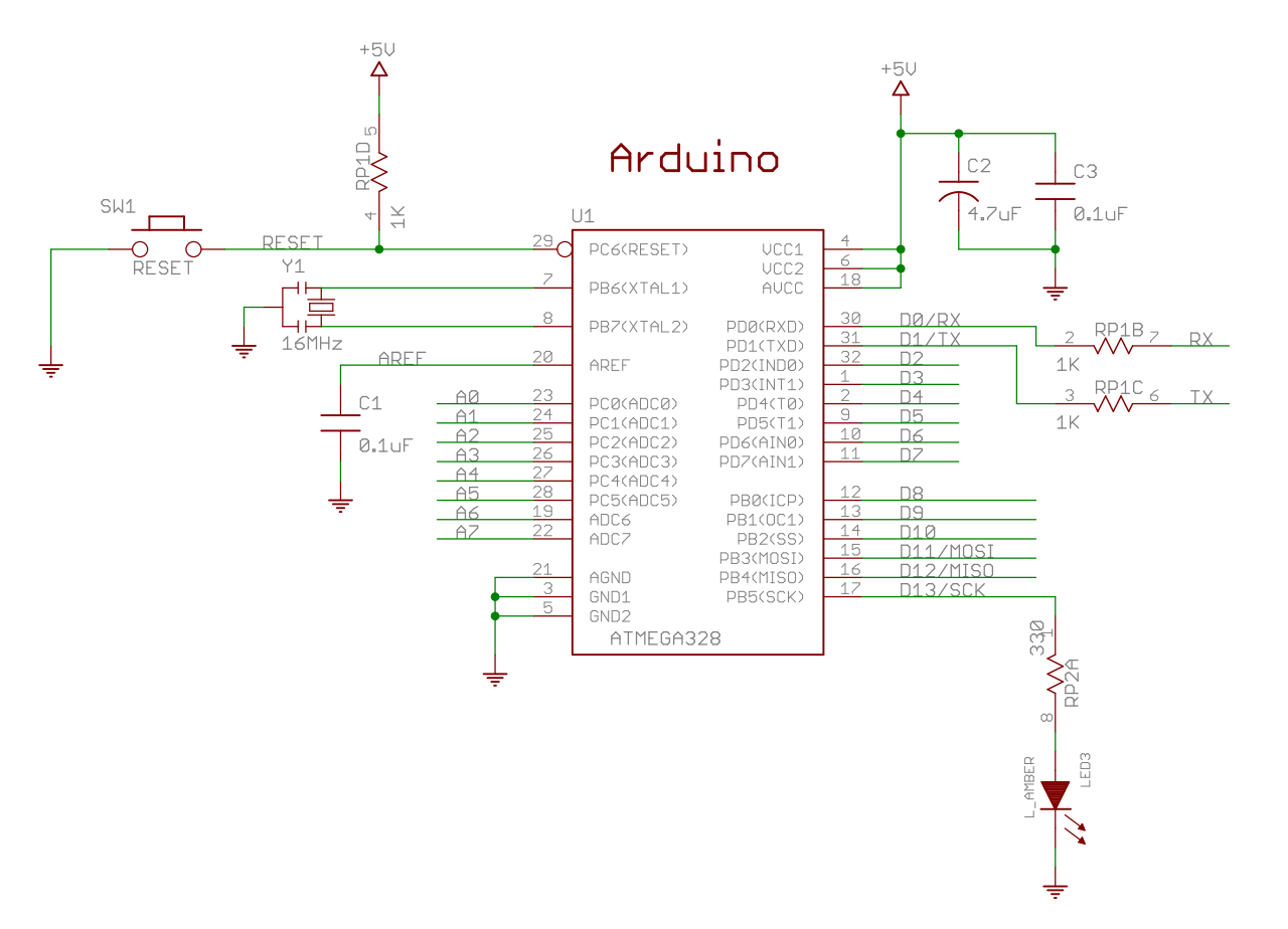
You can follow the pins to various components, and/or directly to the pins of
the board itself. For example, the D0/TX and D1/RX pins on the board are
connected to the PD0 and PD1 pins of the AVR, which are the UART TX and RX pins.
The schematic is confusing at first but gets simpler once you see that every
label is unique, and anywhere a label appears multiple times means they are
connected at those points within the board. So, in the case of the D0 and
D1 pins, they are connected to the AVR directly before the 1k resistors
RP1B and RP1C, which are in turn connected to the TXD and RXD pins of
the FT232RL (via the RX and TX labels, respectively). The FT232RL chip3
is a USB slave to UART converter that connects to the mini-USB connector
(labelled USB-MINI-B%C).
The on-board voltage regulator UA78M054 accepts 7–25 V as input via VIN,
and outputs a regulated 5 V up to 500 mA. Alternatively, USB can power the
board directly. The components thus use a 5 V logic level to communicate binary
signals. A binary signal is a form of modulation (the concept of encoding data
within a signal, in this case electrical) using voltage level to determine a
high value or a low value. The “logic level” determines the actual voltages
used, in our case 5 V for high and 0 V for low. Whether high is
considered a logical 1 (active-high) or a logical 0 (active-low) is dependent on
the pin configuration. When a pin is configured to be active-low, it is usually
labelled with a bar over it (as in RESET{:.overline}) or appended with a #,
but other conventions are also used.
What you can tell from the schematic is that the UART pins of the AVR are directly connected to the pins of the board, but also connected to the FT232R. You can also tell that the FT232R is only connected to the AVR using these 2 pins, beyond a few power and reset pins. So if the computer (via USB) is only able to communicate with the FT232R, then clearly your only method of communicating with the AVR is via the UART. We will look at how to use the UART in a later section.
Using the GNU toolchain
We can use gcc and GNU binutils to program the AVR. For most systems, you will
need to install a separate instance of gcc and binutils built to target AVR.
The toolchain modules are invoked using the prefix avr-; all the same flags
and features are available.
After cross-compiling a program for AVR, the resulting binary needs to be written to the flash and/or eeprom using a “programmer”. The programmer requires a physical connection to the AVR, and uses an algorithm specified in the datasheet (chapter 28) to write the passed program to the chip. The usual tool for interfacing with the programmer is avrdude5. We will be using a programmer called arduino, which is really just the Arduino bootloader6 pre-loaded in the AVR’s memory. The bootloader reads the binary via the UART and writes to the application memory space.
The linker produces ELF-formatted binaries by default, but this programmer doesn’t accept those. Instead, we use Intel hex format binaries:
avr-gcc -mmcu=atmega328p -Wl,--oformat=ihex -o program.hex program.c
Then we tell avrdude to upload the binary:
avrdude -p atmega328p -c arduino -P /dev/ttyUSB0 -b 57600 -D -U flash:w:program.hex:i
How do we know the baud rate should be 57600? Well, avrdude is communicating directly with the bootloader, so all we have to do is look at the bootloader code.
The Microcontroller
So far this doesn’t look too foreign. The differences show up when we try to
actually write a program for the AVR. An MCU does not have the same features as
a microprocessor. There is no kernel/user mode distinction, so the usual
abstracted functions to access operating system services do not exist, as there
is no operating system to speak of. There is only one process, delineated by
the main() function, as process preemption requires a multitasking operating
system (generally facilitated by virtual memory, which MCUs do not have). As
such, your program must do all hardware initialization explicitly. Fortunately,
MCUs are simple enough that this is a reasonable task.
We can use avr-libc7 to provide basic macros and functions. The project attempts to mimic the C standard library, with the limitation that there is no operating system for hardware abstraction. The header file <avr/io.h> supplies macros for the registers of most available chips, and <avr/interrupt.h> supplies macros for interrupt vectors and initialization routines.
Here is the AVR pinout from the datasheet, which you can cross-reference with the Arduino schematic:
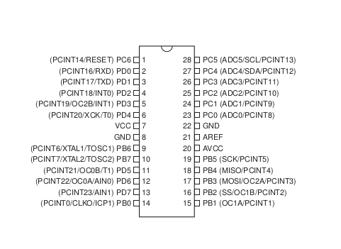
The chip is configured as having 3 “ports”: Port B (corresponding to PBn
pins), Port C (PCn), and Port D (PDn). The idea is that each port has 8
pins (except Port C, read Pin Descriptions in section 1.1) for parallel
communication of bytes when configured for regular digital I/O (the default).
Within each port, each pin also has alternatively configurable functions, which
correspond to the parenthesized labels. So the UART pins, RXD and TXD, are
alternative functions of the Port D pins 0 and 1. Other alternative functions
include clock inputs (XTALn, timers/counters and PWMs (OCnx), external interrupts (PCINTn), serial
protocols like SPI (SCK, MISO, MOSI, SS) and I2C, ADCs (ADCn), and more.
When the MCU begins program execution, no alternative pin functions are
initialized. The only exception is PC6, which is programmed with a fuse bit
to configure reset functionality. All other port pins are set as tri-stated
inputs (high-impedance, i.e. won’t source or sink current), and interrupts are
disabled. The program must then configure how each pin should be used. A
simple program could be to set Port B as an output, and increment the value
input on Port D:
#include <avr/io.h>

int main (void)
{
    DDRB = 0xff;
    while (1) PORTB = 1 + PIND;
    return 0;
}
The DDRx registers determine
whether each pin of the corresponding port is an output or an input. Setting
the register to 0xff configures all Port B pins as outputs. To specify only
certain pins, we use the macro _BV, which is equivalent to (1 << Pxn):
DDRB |= _BV(PB0);      // To set PB0 as an output
DDRB &= ~_BV(PB0);     // To set PB0 as an input
The PORTx registers are writeable I/O memory addresses to toggle outputs on
the respective port. The PINx registers are readable addresses for capturing
inputs. avr-libc hides the specific addresses within these macro definitions
for each chip by including chip-specific header files in the <avr/io.h>
header, switched by the -mmcu compiler flag.
We use an infinite loop so that we are continuously sampling the input at Port
D. Alternatively, we could set PORTB once, and then put the MCU to sleep to
latch the value determined at program start.
The UART
A UART is a simple device for serial communication. Serial means data is sent
in sequence over the same wire, as opposed to having, say, 8 wires transmit a
byte all at once (called parallel communication). When two UARTs are connected
for communication, the transmit pin TX of one is wired to the receive pin RX
of the other, and vice versa. Both the AVR and the FT232R are full-duplex,
meaning they can transmit and receive simultaneously, without having to take
turns (half-duplex). On the host (computer) side, the FT232R driver exposes the
communication as a TTY
interface, which acts like a
pipe to the FT232R. So if you write a character to the TTY (generally will be
/dev/ttyUSB0), a data frame containing that character will pop out at the TXD
pin of the FT232R, which is then connected to the RXD pin of the AVR.
Conversely, if you program the AVR to transmit a character, it will send a data
frame from its TXD pin, which is received by the RXD pin of the FT232R,
which the Linux driver than decodes and writes to the TTY. If you then read
from the TTY (e.g. cat /dev/ttyUSB0), you will retrieve the sent character.
Because UARTs are asynchronous, and do not have a clock line for synchronization, they must synchronize over the same lines used for data transmission. This is only possible if the baud rate (same as the bit rate when using binary modulation) and frame format are agreed upon prior to communication. UARTs use a prescaler to divide the provided clock to a desired baud rate. With a given clock frequency, only a set number of baud rates can be configured.
Section 20.10 of the AVR datasheet has a table of baud rate calculations for commonly-used clock frequencies. Not all standard baud rates are available for every frequency—due to the discrete number of prescaler values available—so the error to the nearest standard baud rate is listed. The range of acceptable errors is tabulated in section 20.8.3. To configure the baud rate, avr-libc provides macros in <util/setbaud.h>. To configure framing, we set the USART Control and Data Registers as outlined in section 20.4. The default is 8 data bits, no parity, and 1 stop bit—commonly used for serial communication with PCs.
For the FT232R, you can set the baud rate via the Linux TTY driver. stty is a
program
used to alter TTY settings, including baud rate and frame format. You can also
affect the TTY programmatically, via the termios
structure in
libc.
The datasheet specifies prescaler options in section 4.2:
[ … ] baud rates are calculated as follows -
\(Baud Rate = \frac{3000000}{n + x}\)
Where \(n\) can be any integer between 2 and 16,384 ( = 214 ) and \(x\) can be a sub-integer of the value 0, 0.125, 0.25, 0.375, 0.5, 0.625, 0.75, or 0.875. When \(n = 1, x = 0\), i.e. baud rate divisors with values between 1 and 2 are not possible.
As an example, we could write a simple program that accepts characters from the host, and sends each character back incremented by one:
#include <avr/io.h>

#define F_CPU 16000000
#define BAUD 38400
#include <util/setbaud.h>

int main(void)
{
    UBRR0H = UBRRH_VALUE;               // UBRR is a 12-bit prescaler register
    UBRR0L = UBRRL_VALUE;               // The value is determined by util/setbaud.h
    UCSR0B = _BV(TXEN0) | _BV(RXEN0);   // This enables the UART pins
    char c;
    while (1) {
        loop_until_bit_is_set(UCSR0A, RXC0);    // Wait for a character
        c = UDR0;
        loop_until_bit_is_set(UCSR0A, UDRE0);   // Ensure the transmit buffer is empty
        UDR0 = c + 1;
    }
    return 0;
}
We set our clock rate F_CPU to match the frequency of the external crystal
seen in the schematic. Then we select a baud rate that has a suitable error for
both the AVR and the FTDI.
Finally, we block on the values of RXC0 and UDRE0 to know when the receive
and transmit buffers are ready for reading and writing, respectively.
Simulating and debugging
We can use simavr to simulate many AVR chips locally, including the ATmega328. simavr has GDB and VCD support, which is especially helpful to those who don’t have access to an oscilloscope, or don’t have an AVR at all.